
Carbon Fiber Structural Repair Design: What Engineers Evaluate Before Installation

The strength of carbon fiber alone does not determine whether a structural repair will perform as intended.
Two walls can exhibit similar cracking but be responding to different forces. Two columns with comparable deterioration may have different load demands, reinforcement layouts, or substrate conditions. Even structures of similar size and construction can require different carbon fiber layouts based on how loads enter, move through, and leave the structural member.
That is why a carbon fiber structural repair should be evaluated as a complete system—not simply as fabric bonded over visible damage.
When reviewing a potential repair, SRS’s in-house engineering team considers the existing structure, anticipated loading, required strengthening capacity, substrate condition, bond requirements, fiber orientation, connections, environmental exposure, and potential failure modes.
The objective is not simply to recommend a product. It is to help develop a repair strategy that addresses the structural demands of the project and can be installed under actual field conditions.
Why Carbon Fiber Repair Is More Than Applying Fabric
A field-laminated carbon fiber reinforced polymer system, commonly called CFRP, combines carbon fiber fabric with a compatible structural epoxy. When installed over a properly prepared substrate, the materials work together as a composite reinforcement system.
For the system to perform as intended, several conditions must be addressed:
The carbon fiber must be positioned within the appropriate load path.
The fibers must be oriented to resist the intended forces.
Sufficient reinforcement must be provided for the required capacity.
Loads must transfer between the existing structure, epoxy, and carbon fiber.
The substrate must be capable of supporting the bonded system.
Adequate bond area and development length must be provided.
Connections and terminations must reflect the intended structural behavior.
Installation must be consistent with the design requirements.
If one part of that system is overlooked, the intended capacity and performance of the CFRP repair may not be achieved.
What Does an Engineering Review Evaluate?
The scope of an engineering review depends on the structure, the proposed repair, and the information available. The following are some of the primary factors that may influence a carbon fiber structural repair design.
1. Existing Structural Condition and Cause of Distress
Visible damage is a starting point, but it does not always identify the complete structural problem.
An engineering review may consider member dimensions, concrete or masonry strength, existing reinforcing steel, crack patterns, corrosion, section loss, deflection, previous repairs, and the condition of adjoining structural elements.
The cause of the distress also matters.
A crack caused by increased loading may require a different repair from cracking caused by corrosion, settlement, impact, inadequate restraint, or a construction deficiency. Strengthening the visibly damaged area without considering the cause can leave another part of the problem unresolved.
The review must determine what remains structurally usable, what requires repair, and how the proposed reinforcement will interact with the existing member.
2. Existing and Anticipated Loading
An important question to consider is, “What forces must the repaired structure resist?”
Depending on the project, an engineer may need to evaluate:
Dead and live loads
Equipment and mechanical loads
Vehicle loads
Lateral earth pressure
Hydrostatic pressure
Wind or seismic forces
Changes in occupancy or building use
The source, magnitude, direction, duration, and distribution of these forces influence the reinforcement layout and the surrounding structural system.
A repair intended to supplement capacity affected by deterioration may require a different approach from a strengthening project designed to support new equipment or increased loading.
For concrete structures, the review may also need to verify that the existing member retains the minimum capacity required by applicable codes without relying entirely on the FRP contribution. Carbon fiber is commonly treated as supplemental reinforcement and should not be assumed to compensate for every underlying stability or capacity deficiency.
3. Load Path and Boundary Conditions

A structural repair requires a clear load path.
The design must consider how forces enter the reinforced area, move through it, and transfer into the surrounding structure. That requires an understanding of how the member is supported and how it connects to adjacent walls, slabs, beams, foundations, or framing.
A wall may span vertically, horizontally, or in two directions. A beam may require flexural strengthening along its span but additional shear reinforcement near a support. A slab repair may need to transfer force beyond a localized deficiency and into an area capable of receiving it.
Strengthening one member can also change the forces transferred to another. The surrounding structure must be capable of supporting the reactions created by the repair.
4. Carbon Fiber Orientation, Spacing, and Number of Layers
Carbon fiber performs primarily in the direction of its fibers. Fiber orientation is therefore a structural design decision—not simply an installation preference.
SRS-600UNI-Directional can be oriented along the primary direction of tensile demand for flexural strengthening of walls, beams, slabs, and other structural members.
Other conditions may require reinforcement in more than one direction, localized crack reinforcement, confinement, shear reinforcement, or a combination of fabrics. SRS-660BI-Directional may be considered when reinforcement is required in two directions or where the design calls for localized crack reinforcement, confinement, or shear strengthening.

Some repair plans use both systems. For example, SRS-600UNI may provide the primary directional reinforcement while SRS-660BI addresses localized cracking, confinement, or multidirectional demands.
Depending on the project, the engineer may determine:
Fiber direction
Strip width and spacing
Number of layers
Total reinforced area
Overlap and transition requirements
Locations requiring supplemental reinforcement
Using more carbon fiber does not automatically create a more effective repair. The reinforcement must be positioned and oriented so it can contribute to the intended structural behavior.
For a closer comparison, see What’s the Difference Between Unidirectional and Bidirectional Carbon Fiber?.
5. Bond Capacity and Development Length
Externally bonded carbon fiber cannot contribute to the repair unless force can transfer between the existing structure and the CFRP system.
The design may need to consider substrate strength, available bond area, epoxy properties, termination locations, and the length required to develop the intended force.
The end of the visible crack is not automatically the correct place to end the reinforcement.
Depending on the application, the carbon fiber may need to extend beyond the distressed area to achieve sufficient bonded length on sound substrate. The required length is project-specific. In some cases, the existing geometry may prevent the carbon fiber from developing its full tensile capacity through bond alone. When sufficient bonded length cannot be achieved, supplemental carbon fiber anchorage may be required.
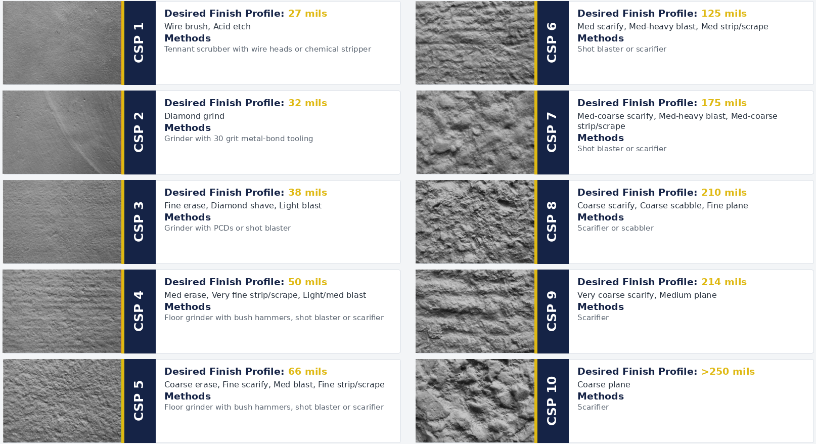
6. Substrate Condition and Surface Preparation

A bonded CFRP system depends on the condition of the material directly beneath it.
Paint, laitance, contamination, loose mortar, deteriorated concrete, surface irregularities, and unresolved moisture conditions can interfere with adhesion. Cracks, open mortar joints, spalls, and voids may also require repair and surface filling before carbon fiber is installed.
Surface preparation may include:
Removing coatings and unsound material
Mechanically preparing and cleaning the surface
Repairing cracks
Filling voids and surface irregularities
Restoring deteriorated concrete or masonry
Evaluating the remaining substrate
The correct reinforcement layout applied over an unsuitable substrate can dramatically reduce the performance of the carbon fiber.
Learn more about concrete surface-profile requirements for CFRP installation.
7. Anchorage, Connections, and Termination Details
Anchorage requirements depend on what the repair is being asked to do.
Some CFRP designs may develop the required force through the available bonded length. Other conditions may require supplemental FRP anchors, transverse reinforcement, mechanical connections, tiebacks, or another termination detail.
Those requirements depend on the loading, substrate, geometry, available development length, boundary conditions, and potential failure modes. There is no single anchorage detail that applies to every externally bonded carbon fiber repair.
The receiving structure must also be considered. Adding a stronger connection does not resolve the problem if the adjacent slab, footing, wall, or framing cannot support the transferred reaction.
8. Potential Failure Modes
The most visible damage is not always the condition that governs the repair.
Depending on the structure, the engineering review may need to consider:
Flexural failure
Shear failure
Concrete or masonry substrate failure
Anchorage or connection failure
Column confinement deficiencies
Punching shear
Sliding, tipping, or overturning
Failure of an adjacent structural member
Strengthening one area can change how forces are distributed through the structure. The review may therefore need to consider whether the proposed reinforcement affects other members or connections. An effective repair should address the governing condition without simply transferring the problem to another part of the structure.
9. Environmental Exposure and Long-Term Protection
Interior, exterior, industrial, marine, and civil infrastructure projects can experience very different service conditions.
The review may need to consider:
Temperature and moisture
Chemical exposure
Abrasion or impact
Ultraviolet exposure
Freeze-thaw conditions
Fire-resistance requirements
Protective coatings or finishes
These conditions can influence material selection, installation requirements, inspection, and the protection placed over the completed CFRP system.
10. Constructibility, Inspection, and Quality Assurance
A repair plan must account for how the work will be installed.
Project drawings and details may need to consider access, working clearances, surface geometry, obstructions, mechanical systems, occupied spaces, installation sequencing, and other field conditions.
These factors can influence strip widths, reinforcement locations, material formats, splice locations, equipment requirements, and construction sequencing.
The design documents may also establish requirements for:
Substrate testing
Surface-profile verification
Material storage
Environmental conditions during installation
Resin proportioning and mixing
Fiber saturation
Removal or repair of voids
Cure verification
Pull-off testing
Final inspection
Inspection of protective finishes
The required level of inspection and testing varies by project. These measures help determine whether the installed system is consistent with the assumptions and requirements used in the design.
Carbon Fiber May Be Only One Part of the Repair Plan
Carbon fiber reinforcement may provide the supplemental capacity required by a repair, but it does not eliminate the need to address existing damage or prepare the structure for installation.
Depending on the project, the complete repair plan may include:
Structural crack injection
Repair of spalls, voids, or deteriorated areas
Chemical treatment of exposed or corroded reinforcing steel
Surface leveling before CFRP installation
Supplemental anchors, connections, or tiebacks
Corrosion-mitigation treatments when project conditions require them
Protective coatings or finishes over the completed system
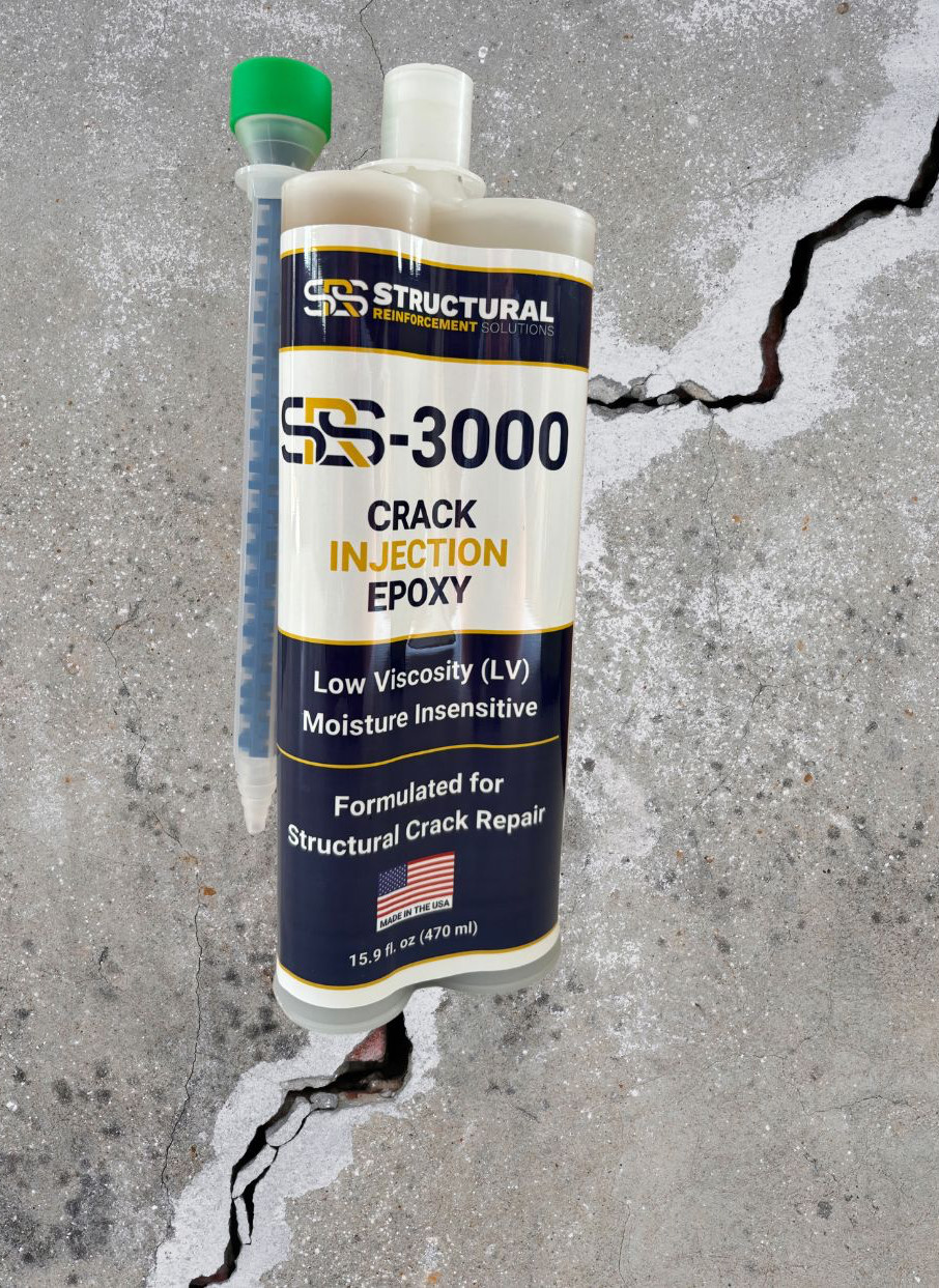

For example, SRS-3000 Crack Injection Epoxy may be used when cracks require structural injection before reinforcement is installed. SRS-2100 Concrete Repair Paste may be used to set injection ports, seal the crack surface during injection, or complete other localized surface repairs when appropriate.
SRS-2000 Structural Repair Paste can be considered for filling large voids, patching damaged areas, and correcting surface irregularities as part of substrate preparation.
The specified carbon fiber fabric is then installed with the compatible SRS-1000 Structural Epoxy Resin, which bonds the fabric to the prepared substrate and saturates the fibers to form the composite system.
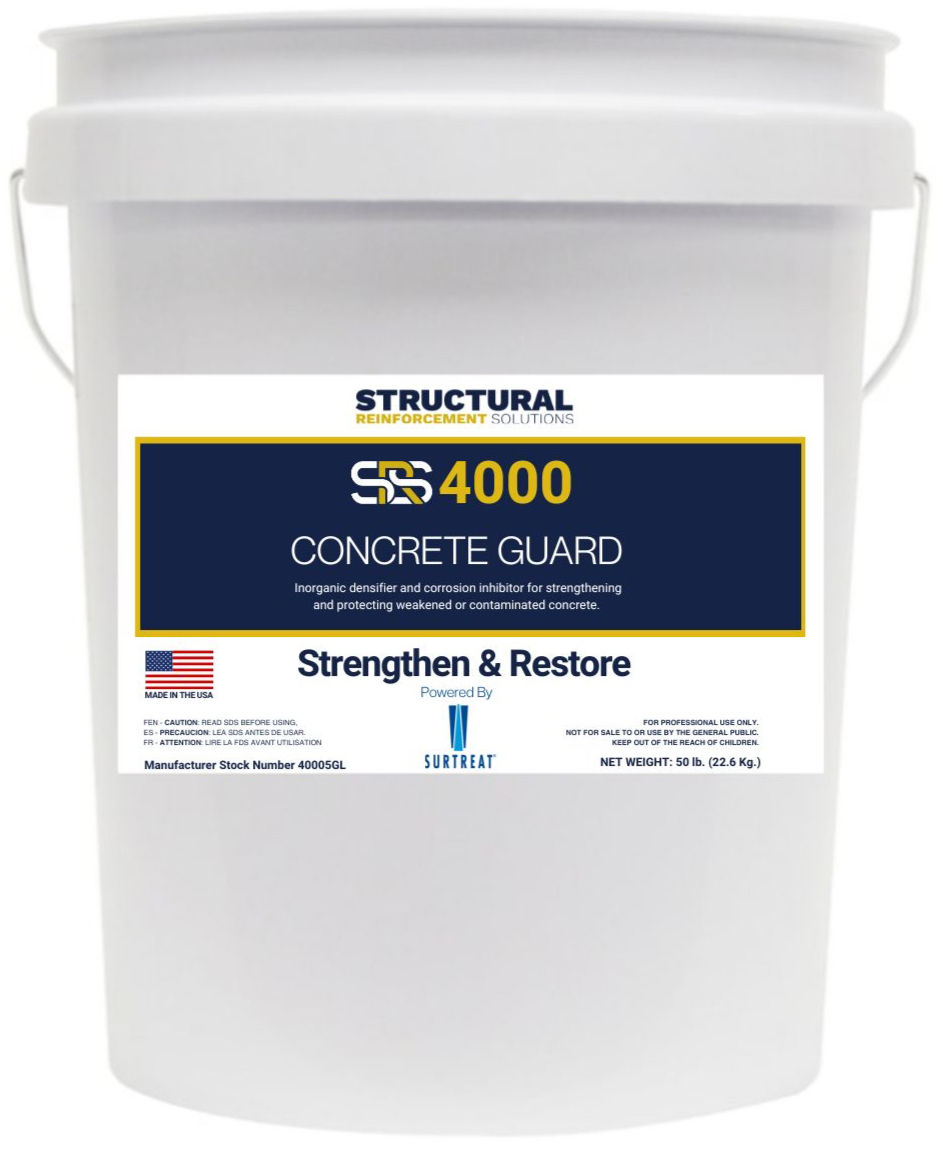

When concrete deterioration includes corrosion-related conditions, SRS-4000 Concrete Guard and SRS-4100 Steel Guard may also be considered as part of a broader repair and protection strategy when appropriate. Their use depends on the condition of the concrete, reinforcing steel, and service environment.
Not every project requires every product. The appropriate combination depends on the cause of distress, substrate condition, exposure, structural demands, and repair objectives.
This is why the repair should be planned as a system rather than approached as a single product applied over visible damage.
Bowed Wall Stabilization: An Example of the Complete-System Approach

A bowed basement wall provides a useful example of why engineering considerations extend beyond strap spacing
Lateral earth pressure generally increases with depth. Surcharge loads, groundwater, soil conditions, wall geometry, and support at the top and bottom can change the magnitude and distribution of the forces acting on the wall.
Wall height, thickness, material properties, existing reinforcement, and boundary conditions also influence structural demand.
When vertical flexure governs, properly designed carbon fiber reinforcement oriented vertically on the interior face may provide supplemental tensile capacity. Depending on wall geometry, loading, and structural behavior, horizontal or localized reinforcement may also be appropriate.
The observed failure mode matters. A wall bowing between adequate top and bottom supports is not necessarily behaving the same way as a wall that is tipping, rotating, sliding, or shearing near its base.
Depending on the project, the repair may rely on verified existing supports or incorporate supplemental connections, restraint, or another stabilization method.
The appropriate solution comes from evaluating the structure and its load path—not from assuming every foundation wall requires the same carbon fiber or anchorage configuration.
For more detail, see:
How Engineering Changes the Repair: Four Project Examples
The value of an engineering review becomes clearer when comparing projects with different structural demands.

Retaining Wall Strengthening in Palm Springs, California
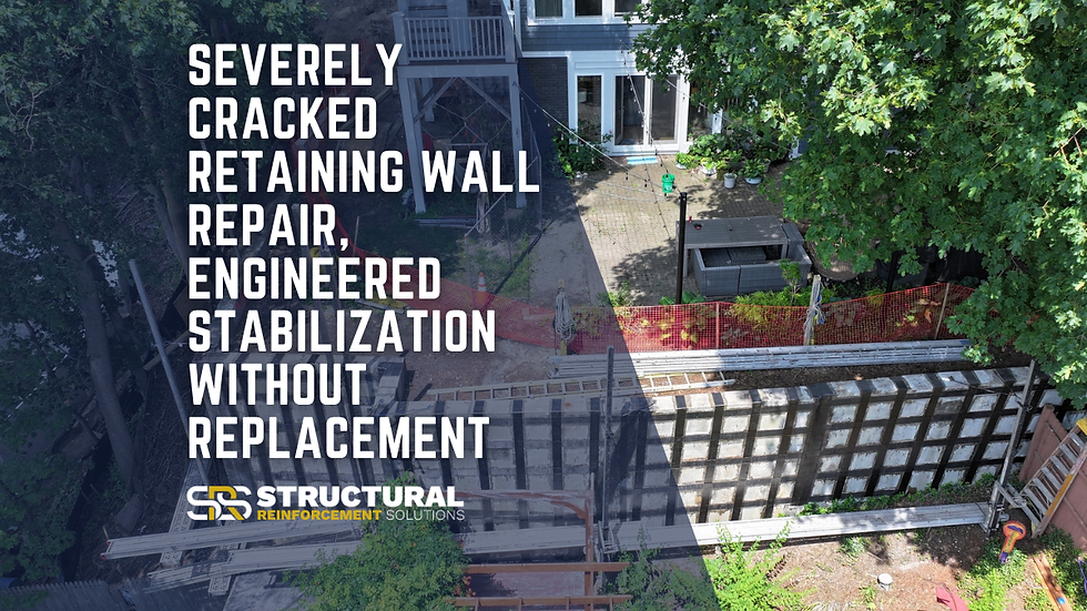
A 650-foot retaining wall exhibited cracking, tilting, and soil-pressure-related distress. The repair combined CFRP reinforcement with structural steel tiebacks because strengthening the wall element and providing overall restraint both had to be considered.

Post-Tensioned Slab Strengthening in Vero Beach, Florida
Construction deficiencies and misaligned tendons created flexural stress and punching-shear concerns in a post-tensioned slab. The CFRP repair plan used different reinforcement configurations to address the directional flexural demand and localized shear conditions.
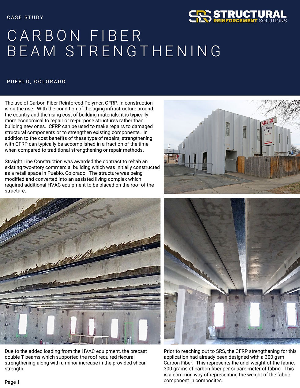
Beam Strengthening for Added HVAC Loads in Pueblo, Colorado
New mechanical equipment increased the load on existing precast double-tee beams. The engineering review evaluated the increased demand and developed a CFRP layout intended to provide the required supplemental capacity while accounting for the size and configuration of the existing members.

Brick Column Reinforcement in Zanesville, Ohio
A critical brick support column inside an active industrial facility required strengthening under a limited production schedule. The repair plan had to address the condition of the masonry surface, voids and irregularities, the confinement layout, access, and installation sequencing.
All four projects used carbon fiber, but they did not use one universal layout. The repair details followed the structural demands, substrate, load path, failure modes, and field conditions of each project.
Additional examples can be found in the SRS Structural Repair Case Study Library.
Engineering Support from the Foundation Up
The same complete-system approach can be applied to many structural repair and strengthening projects, including:
Retaining walls subjected to soil and hydrostatic pressure
Concrete and masonry columns requiring confinement
Beams and slabs carrying increased loads
Post-tensioned slab deficiencies
Parking structures and industrial facilities
Bridge components and civil infrastructure
Seawalls, docks, and marine structures
Structural crack reinforcement
Change-of-use and equipment-loading upgrades
The appropriate reinforcement layout, fabric orientation, number of layers, supporting repair materials, and connection details depend on the conditions and requirements of the individual project.
What Should You Submit for an SRS Project Review?
Clear project information helps the engineering team understand the existing structure and identify what may be required for the review.

Useful information may include:
Structural drawings or sketches
Clear photographs of the damaged area and surrounding structure
Member dimensions
Crack locations and approximate widths
Areas of deterioration or exposed reinforcing steel
Existing and proposed loads
Reports or requirements from the engineer of record
Site-access limitations
Environmental exposure conditions
Project schedule and submittal requirements
Not every item will be available at the beginning of a project. SRS can help identify additional information that may be needed as the review progresses.
From Engineering Review to a Buildable Repair Plan
SRS’s in-house engineering team provides specialized support for evaluating and developing carbon fiber strengthening strategies.
When a project has an existing structural engineer of record, SRS can coordinate the CFRP requirements with that engineer so the reinforcement, reactions, connections, and surrounding structural system can be considered together.
Depending on the project scope, available information, and jurisdictional requirements, SRS engineering support may include:
A project-specific strengthening strategy
Carbon fiber layout and orientation
Layering and spacing requirements
Surface-preparation and repair details
Anchorage and termination details
Installation notes
Material takeoffs
Calculations or project-specific drawings when included in the scope
This information can help contractors define the work, estimate material requirements, prepare project pricing, and approach installation with a clearer plan.
Frequently Asked Questions About Carbon Fiber Structural Repair Design
Does every carbon fiber repair require an engineered design?
Project requirements depend on the structure, application, local codes, and authority having jurisdiction. Standardized systems may be appropriate for certain defined conditions. Damaged, heavily loaded, complex, or nonstandard structures may require a project-specific engineering evaluation.
How does an engineer determine the number of carbon fiber layers?
The number of layers may be influenced by the required supplemental capacity, member geometry, existing reinforcement, substrate properties, CFRP design values, bond limitations, fiber orientation, environmental reductions, and governing failure mode.
Adding more layers is not automatically beneficial if bond, development, substrate capacity, or another part of the structure governs the design.
How is carbon fiber strip spacing determined?
Spacing may be influenced by how forces are distributed through the member, required capacity, strip width, fiber properties, existing reinforcement, substrate conditions, and governing design limits. It should not be selected solely from the visible crack pattern.
Does every externally bonded CFRP system require mechanical anchors?
No universal anchorage detail applies to every project. Some designs may develop the required force through bonded length. Others may require FRP anchors, transverse reinforcement, mechanical connections, tiebacks, or another detail.
The requirement depends on the application, geometry, substrate, loading, boundary conditions, and potential failure modes.
Why is surface preparation important before CFRP installation?
Externally bonded carbon fiber transfers force through the epoxy and into the underlying substrate. Coatings, contamination, weak concrete, loose mortar, voids, and deteriorated material can reduce bond performance.
The surface may require preparation and repair before the CFRP system is installed.
Can carbon fiber strengthen a retaining wall without tiebacks?
CFRP may increase the flexural or shear capacity of a retaining-wall element, but surface-applied reinforcement does not correct every global stability condition.
Sliding, overturning, foundation or bearing deficiencies, inadequate restraint, groundwater pressure, and overall slope stability may also need to be evaluated.
Depending on the governing condition, the CFRP repair may need to be coordinated with tiebacks or another stabilization system.
Learn more about retaining-wall structural crack repair with carbon fiber.
Is carbon fiber the only material included in a CFRP repair plan?
Not necessarily. The existing structure may require crack injection, void filling, surface leveling, concrete or masonry restoration, reinforcing-steel treatment, supplemental connections, or protective finishes before or after CFRP installation.
The materials included in the repair plan depend on the existing damage, structural demands, substrate, and service environment.
Can SRS coordinate with the project’s structural engineer?
Yes. SRS can provide specialized CFRP design support and coordinate with the project’s structural engineer. Depending on the project scope, this may include technical information, reinforcement layouts, calculations, repair details, material takeoffs, and application guidance.
Related Carbon Fiber Articles and Structural Repair Projects
Related SRS Articles
Related SRS Projects
Save this post for your next structural repair—or submit your drawings, photos, and project details for an SRS engineering review.
Toll Free 1-888-292-2592


Comments